Cutting speed chart pdf Napier

Choosing Cutting Parameters/Calculating Cutting Speed and Milling operations remove material by feeding a workpiece into a rotating cutting tool with sharp teeth, such as an end mill or face mill. Calculations use the desired tool diameter, number of teeth, cutting speed, and cutting feed, which should be chosen based on the specific cutting conditions, including the workpiece material and tool material.
Cutting speeds
Speeds Feeds & DOC. morsecuttingtools.com Taps & Dies 197 STANDARD TAPS SPEED RECOMMENDATIONS SPEEDS shown are suggested starting points only and may be increased or decreased depending on actual material and machining conditions. Start conservatively and increase until the machining cycle is optimized., GERBER PLATINUM FEED SPEED CHART The feed speeds and depths per pass are recommended based on specific materials tested by Gerber. All materials and manufacturers vary and may require reduced feeds and speeds. C.E.L. в€’ Cutting Edge Length. The distance from the cutting end of the bit.
Foam Cutting Spiral Router Bits Operating RPM: 18,000 Square End Tool No. ГD Chip Load Per Tooth 46269 1/8 0.002 – 0.004" "46270 1/8 0.002" – 0.004" 46562 1/8 0.002" – 0.004" 46564 1/8 0.002" – 0.004" Foam-Cutting-Speed-Chart Created Date: 5/4/2017 8:45:16 AM Cost-effective cutting through thick and thin. 2 Application The best solution for your application There is a reason for the wide range of laser cutting machines available from TRUMPF: You should always be able to find the best solution for your application. In doing so, there are Active Speed Control monitors the cutting process in real
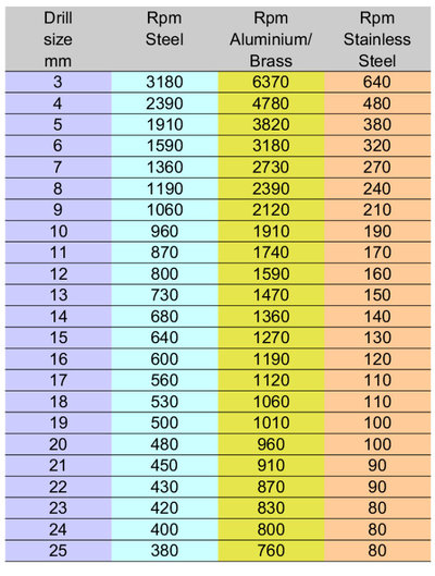
HIGH SPEED STEEL DRILLS - METRIC Recommended Cutting Speeds in R.P.M. 1.0 970 3878 9695 14542 1.5 647 2589 6474 9711 2.0 485 1941 4853 7280 2.5 388 1552 3882 5823 3.0 323 1294 3234 4851 3.5 277 1108 2772 4158 4.0 243 970 2425 3638 5.0 194 776 1941 2911 6.0 162 647 1617 2426 7.0 139 554 1386 2079 8.0 121 485 1213 1819 9.0 108 431 1078 1617 10.0 TORCH SETUP 3-8 powermax45 Service Manual Choose the consumables (cut charts) WARNING INSTANT-ON TORCHES PLASMA ARC CAN CAUSE INJURY AND BURNS I O The plasma arc comes on im me di ate ly when the torch trigger is activated.
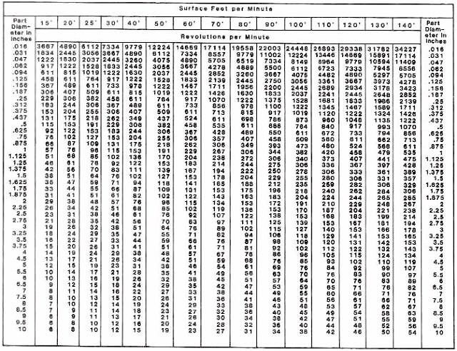
3/28/2010В В· Find the type of material you are cutting at the top of the chart. The type of material will be highlighted in a set of columns. Follow these columns down matching up with the cutter diameter in the left column. H: is the speed for HSS, C: is for Coated (HSS +30%). The row below the material type is the Cutting Speed in Feet per Minute. morsecuttingtools.com Taps & Dies 197 STANDARD TAPS SPEED RECOMMENDATIONS SPEEDS shown are suggested starting points only and may be increased or decreased depending on actual material and machining conditions. Start conservatively and increase until the machining cycle is optimized.
The cutting speed is 35 metres per minute and the feed is 0.5mm per revolution. Average cutting speed expressed in meter per minute for different operations in a lathe using an H.S.S. tool. Average cutting speed, feed and depth of cut for different tool materials: Cutting Tool Signature. Milling operations remove material by feeding a workpiece into a rotating cutting tool with sharp teeth, such as an end mill or face mill. Calculations use the desired tool diameter, number of teeth, cutting speed, and cutting feed, which should be chosen based on the specific cutting conditions, including the workpiece material and tool material.
Victor Tip Charts PROPANE, LPG and NATURAL GAS Cutting Tip Chart Cutting Tip Series GPN and HPN Metal Thickness Tip Size Cutting Oxygen (PSIG)*** Preheat Oxygen (PSIG)* Preheat Fuel Gas (PSIG) Speed I.P.M. Kerf Width 1/8" 000 20/25 FOR 3-HOSE MACHINE TORCHES ONLY SEE TABLE BELOW 3/5 24/28 .04 1/4" 00 20/25 3/5 21/25 .05 3/8" 0 25/30 3/5 20/24 .06 speed of a mechanical component. • Surface Speed (sfm or m/min) – It is the speed difference (relative velocity) between the cutting tool and the surface of the workpiece it is operating on. It is expressed in units of distance along the workpiece surface per unit of time, typically surface feet per minute (sfm) or meters per minute(m/min).
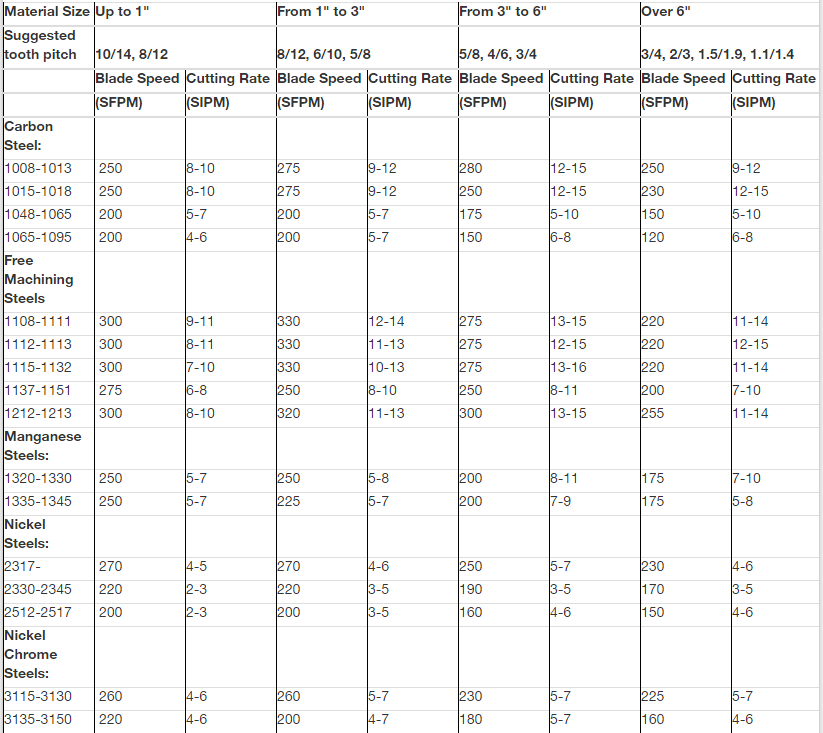
Cutting Speeds and Rates for Bi-Metal & Carbide Blades Bi-Metal Carbide Steel Type Steel Specification Blade Speed Cutting Rate Blade Speed Cutting Rate British EN Numbers U.S.A. (AISI) Metres per Minute Square cm per Minute Metres per Minute Square cm per Minute Work Material Low Carbon Steels EN 14-32-36 EN2, EN3 EN80M, EN15AM EN1A, EN7 Chart 2. The differences in the operating cost are based on the maintenance and the efficiency of the style of laser being used. Chart #3 illustrates the different efficiencies for the various cutting lasers. Chart 3. The final piece of the puzzle for laser processing is the cutting speed.
Foam Cutting Spiral Router Bits Operating RPM: 18,000 Square End Tool No. ГD Chip Load Per Tooth 46269 1/8 0.002 – 0.004" "46270 1/8 0.002" – 0.004" 46562 1/8 0.002" – 0.004" 46564 1/8 0.002" – 0.004" Foam-Cutting-Speed-Chart Created Date: 5/4/2017 8:45:16 AM METAL MILLING SPEED CHART - PDF Printable Metal cutting milling speeds for different materials. The chart is based on mild steel to the hardest tool steel milling applications. The column of the milling chart list the Brinell Hardness, material condition and the SFPM for HSS and Carbide tools.
Download, Fill In And Print Drill Press Speed Chart Pdf Online Here For Free. Drill Press Speed Chart Is Often Used In Drill Speed Chart, Drill Chart And Life. Drill Press Speed Chart. ADVERTISEMENT. Lubricate drill with oil when cutting steel. 1/16. 3/16. Sutton Tools have made the tool selection for cutting different materials easy by applying colour coded bands to the shanks of the tools which relates to the material it is best suited to.
Band speed refers to the rate at which the blade cuts across the face of the material being worked. A faster band speed achieves a higher, more desirable shear plane angle and hence more efficient cutting. This is usually stated as FPM (feet per minute) or MPM (meters per minute). Band speed is restricted, however, by the machinabil- results from cutting tools. Improper speeds and feeds often cause low production, poor quality, and damage to the tool. Speeds that are too high or feeds that are too light can lead to rapid wear and dulling of the cutter, reducing tool life. Speed is measured in peripheral feet per minute. It is often referred to as cutting speed or surface speed.
Speed Settings for Accessories. Before using any power tool, be sure that you read and understand all instructions in the owner’s manual. Failure to understand the safe use of any power tool or product may result in serious personal injury. Cutting Speed (Vc) SFM ISO Materials Rm and Hardness CVD Coated NL200 NL250 NL300 NL400 NL920 min. - max. min. - max. min. - max. min. - max. min. - max. Cutting Speed (vc) SFM Material Guide – Key to Recommended Inserts Material Designation P Unalloyed Steels Stainless Steels Cast IronsP Alloyed Steels PH Stainless Aluminum & AlloysM M KNS
OXY/ACETYLENE WELDING AND CUTTNG
Lathe machine formula Cutting speed Depth of cut feed. Band Saw Blade Speed Chart . Material HIGH SPEED STEELS AUSTENITIC STAINLESS STEELS FERRITIC 1-3 STAINLESS * Reduce speed 40% when cutting dry. * Reduce speed 50% when using carbon blades. Material LOW CARBON BI-METAL BAND SAW BLADE SPEED AND FEED CHART 3"-6" FPM 260 210 175 260 220 275 290 200 240 190 200 190 170 180 160 160 160 140, Feeds and Speeds Charts • August 1, 2016 Introduction A challenge of getting a good CNC cut is in selecting the best cutting speed (feed rate) and router/ spindle RPM (speed of rotation). 50%. If doing this, it will be necessary to calculate the feed rate and speed instead of using the chart. Example using a 1/4” or 0.125” bit.
Lathe machine formula Cutting speed Depth of cut feed. DRILL PRESS SPEED CHART Recommended operating speeds (RPM) Accessory Softwood (Pine) Hardwood (Hard Maple) Acrylic Brass Aluminum Steel Shop Notes Twist drill bits* 3000 3000 1500 750 3000 1500 750 500 2500 2000 1500 NR 3000 1200 750 400 3000 2500 1500 1000 3000 1000 600 350 Lubricate drill with oil when cutting steel 1/ 8" or thicker. Use, Twist Drill Feeds (Feed per Revolution) Drill Size Inches Drill Feed Inches Drill Size Metric Drill Feed Millimeter 1/8" and smaller 0.001" to 0.002 3mm and smaller .02mm to 0.05mm Cutting Speed = Cutting Speed for the material being cut/worked. Diameter = The Diameter of whatever is turning..
CUTTING SPEEDS & RATES BI-METAL & CARBIDE BLADES

Cutting conditions setting guide. – Compatibility chart between cutting edges and workpiece – Cutting speed varies along cutting edges as a function of distance from axis of rotation – Zero Relative velocity at drill point (no cutting) – A large thrust force to drive the drill forward • Chip removal https://en.wikipedia.org/wiki/Rake_angle GERBER PLATINUM FEED SPEED CHART The feed speeds and depths per pass are recommended based on specific materials tested by Gerber. All materials and manufacturers vary and may require reduced feeds and speeds. C.E.L. − Cutting Edge Length. The distance from the cutting end of the bit.
To begin oxygen/acetylene welding or cutting, open the (see chart on page 13), this ensures that any air or oxygen is purged from the hose. Repeat the procedure for the oxygen side. towards the body along the line of cut at a speed recommended in the data tables. Band Saw Blade Speed Chart . Material HIGH SPEED STEELS AUSTENITIC STAINLESS STEELS FERRITIC 1-3 STAINLESS * Reduce speed 40% when cutting dry. * Reduce speed 50% when using carbon blades. Material LOW CARBON BI-METAL BAND SAW BLADE SPEED AND FEED CHART 3"-6" FPM 260 210 175 260 220 275 290 200 240 190 200 190 170 180 160 160 160 140
CUTTING DATA RECOMMENDATIONS Uddeholm Corrax Machining data are always dependent on the actual operation, the machine tool and the cutting data used. The best rule of thumb for proper cutting speed is the color of the chip when cutting steel. Using a high-speed steel drill bit the chips should never be turning brown or blue. Straw colored chips indicate that you are on the maximum edge of the cutting speed for your cutting conditions.
cutting speed. Cutting conditions setting guide Referring to the cutting rate given in the chart below, adjust the cutting speed so that the cutting time calculated as described in the page on the left can be obtained Note: lf the blade is a new one, perform break-in cutting. (See separate sheet for … The speed that the tool or the work moves at the point of cut. SPINDLE SPEED IS NOT THE CUTTING SPEED! Spindle RPM = SFM/ Dia. X 3.82 x tooling correction factor . Speed chart . Cutting speed recommendations . Material type . Surface feet per min (SFM) Steel (structural)
Band Saw Blade Speed Chart . Material HIGH SPEED STEELS AUSTENITIC STAINLESS STEELS FERRITIC 1-3 STAINLESS * Reduce speed 40% when cutting dry. * Reduce speed 50% when using carbon blades. Material LOW CARBON BI-METAL BAND SAW BLADE SPEED AND FEED CHART 3"-6" FPM 260 210 175 260 220 275 290 200 240 190 200 190 170 180 160 160 160 140 Turning Speeds & Feeds - RPM Calculations . Cutting speed is the speed at the outside edge of the part as it is rotating. This is also known as surface speed. In Table 4 you will find a typical recommended cutting speed chart. Table 4. Recommended Cutting Speeds in Feet per Minute
Choosing Cutting Parameters/Calculating Cutting Speed and Feed – INCH For Ball Nose Inserts Cutting Parameters / Cutting Speed & Feed Table 1 - Cutting Conditions for Using Steel Shank Holders Working Material Hardness Grade SFM Feed fn (inch/Rev) Insert Diameter (inch) Ap Max Ae Max 0.250 0.312 0.375 0.500 0.625 0.750 1.000 1.250 The speed that the tool or the work moves at the point of cut. SPINDLE SPEED IS NOT THE CUTTING SPEED! Spindle RPM = SFM/ Dia. X 3.82 x tooling correction factor . Speed chart . Cutting speed recommendations . Material type . Surface feet per min (SFM) Steel (structural)
Fig. 2: Comparison of the specific cutting force of three copper alloys with a case-hardened steel based on data from DKI and from reference [4] Abb 2Abb. 2: V lihd ifih Shi k f d Ki f l iVergleich der spezifischen Schnittkraft von drei Kupferlegierungen Cutting Speed (Vc) SFM ISO Materials Rm and Hardness CVD Coated NL200 NL250 NL300 NL400 NL920 min. - max. min. - max. min. - max. min. - max. min. - max. Cutting Speed (vc) SFM Material Guide – Key to Recommended Inserts Material Designation P Unalloyed Steels Stainless Steels Cast IronsP Alloyed Steels PH Stainless Aluminum & AlloysM M KNS
speed of a mechanical component. • Surface Speed (sfm or m/min) – It is the speed difference (relative velocity) between the cutting tool and the surface of the workpiece it is operating on. It is expressed in units of distance along the workpiece surface per unit of time, typically surface feet per minute (sfm) or meters per minute(m/min). To begin oxygen/acetylene welding or cutting, open the (see chart on page 13), this ensures that any air or oxygen is purged from the hose. Repeat the procedure for the oxygen side. towards the body along the line of cut at a speed recommended in the data tables.
Sutton Tools have made the tool selection for cutting different materials easy by applying colour coded bands to the shanks of the tools which relates to the material it is best suited to. Self-propelled, it has an infinitely variable speed control to suit any application. HOB-O gives you the precision of drilling … the speed of flame boring … and the convenience of a portable tool costing less than one 4'' high speed drill bit. Flame Cutting Handbook.p65 5/9/2007, 8:06 AM4
ate a higher cutting temperature at any given cutting speed, thereby m aking it necessary to use a slower speed, for the cutting temperature must always be kept within the limits that can be sustained by the cutting t ool without failure. Hardness, then, is an important prop-erty that must be considered when machining a given metal. Composite, Fiberglass & Phenolic Cutting ZrN Coated Router Bits Operating RPM: 18,000 INDUSTRIAL Depth of Cut: 1 x D Use recommended chip load 2 x D Reduce chip load by 25% 3 x D Reduce chip load by 50% * SFM Surface feet per minute Simple Machining Calculations: To find RPM: SFM x 3.82 / diameter of tool To find SFM: 0.262 x diameter of tool x RPM
Feeds and Speeds Charts • August 1, 2016 Introduction A challenge of getting a good CNC cut is in selecting the best cutting speed (feed rate) and router/ spindle RPM (speed of rotation). 50%. If doing this, it will be necessary to calculate the feed rate and speed instead of using the chart. Example using a 1/4” or 0.125” bit Cost-effective cutting through thick and thin. 2 Application The best solution for your application There is a reason for the wide range of laser cutting machines available from TRUMPF: You should always be able to find the best solution for your application. In doing so, there are Active Speed Control monitors the cutting process in real
BOC Guidelines for Welding and Cutting. 2 Welcome to a better way of cutting, welding, 7.1 Filler Rod and Flux Selection Chart 23 7.2 How to Improve Weld Quality 24 8.0 Joining Processes 28 19.4 BOC 3 Seat Oxy-Acetylene Cutting Nozzles 55 19.5 BOC 3 Seat … Chart 2. The differences in the operating cost are based on the maintenance and the efficiency of the style of laser being used. Chart #3 illustrates the different efficiencies for the various cutting lasers. Chart 3. The final piece of the puzzle for laser processing is the cutting speed.
Cutting data recommendations Uddeholm
Victor Tip Charts Amazon S3. Milling operations remove material by feeding a workpiece into a rotating cutting tool with sharp teeth, such as an end mill or face mill. Calculations use the desired tool diameter, number of teeth, cutting speed, and cutting feed, which should be chosen based on the specific cutting conditions, including the workpiece material and tool material., To begin oxygen/acetylene welding or cutting, open the (see chart on page 13), this ensures that any air or oxygen is purged from the hose. Repeat the procedure for the oxygen side. towards the body along the line of cut at a speed recommended in the data tables..
Lathe machine formula Cutting speed Depth of cut feed
Choosing Cutting Parameters/Calculating Cutting Speed and. you will have to calculate the feed rate and speed yourself instead of using our chart. Example using a 1/4” or 0.125” bit – Straight V Carbide Tipped Endmill SB# 13642: You decide to use this bit for soft wood, and decide to use this to a depth of cut of 1/2” (2 times the, Shear-cutting countersink Countersink screw pilot bit Taper drill bit with countersink Drum Plug cutter Polishing Wheel Flap sander DRILL PRESS SPEED CHART Recommended operating speeds (RPM) From tne of Aluminum Steel Better Homes arKl Gardensø WOOD MAGAZINE Shop Notes Black & Decker Bullet pilot-point bit Forstner Multi-spur Glass- and-tile.
BOC Guidelines for Welding and Cutting. 2 Welcome to a better way of cutting, welding, 7.1 Filler Rod and Flux Selection Chart 23 7.2 How to Improve Weld Quality 24 8.0 Joining Processes 28 19.4 BOC 3 Seat Oxy-Acetylene Cutting Nozzles 55 19.5 BOC 3 Seat … CUTTING DATA RECOMMENDATIONS Uddeholm Corrax Machining data are always dependent on the actual operation, the machine tool and the cutting data used.
Download, Fill In And Print Drill Press Speed Chart Pdf Online Here For Free. Drill Press Speed Chart Is Often Used In Drill Speed Chart, Drill Chart And Life. Drill Press Speed Chart. ADVERTISEMENT. Lubricate drill with oil when cutting steel. 1/16. 3/16. results from cutting tools. Improper speeds and feeds often cause low production, poor quality, and damage to the tool. Speeds that are too high or feeds that are too light can lead to rapid wear and dulling of the cutter, reducing tool life. Speed is measured in peripheral feet per minute. It is often referred to as cutting speed or surface speed.
morsecuttingtools.com Taps & Dies 197 STANDARD TAPS SPEED RECOMMENDATIONS SPEEDS shown are suggested starting points only and may be increased or decreased depending on actual material and machining conditions. Start conservatively and increase until the machining cycle is optimized. Twist Drill Feeds (Feed per Revolution) Drill Size Inches Drill Feed Inches Drill Size Metric Drill Feed Millimeter 1/8" and smaller 0.001" to 0.002 3mm and smaller .02mm to 0.05mm Cutting Speed = Cutting Speed for the material being cut/worked. Diameter = The Diameter of whatever is turning.
Suggested Cutting Speeds for Machining Material Cutting Speed, m min Turning Drilling Milling HSS Carbide HSS HSS Carbide Mild steel 20-35 90-135 20-30 20-35 75-130 Aluminum 150-180 335-365 30-120 150-180 335-365 Free machining brass 90-105 180-200 50-55 90-105 180-200 Cut charts The following Cut charts show the consumable parts, cutting speeds and the gas and torch settings required for each process. The numbers shown in the Cut charts are recommended to provide high-quality cuts with minimal dross. Because of
3/28/2010В В· Find the type of material you are cutting at the top of the chart. The type of material will be highlighted in a set of columns. Follow these columns down matching up with the cutter diameter in the left column. H: is the speed for HSS, C: is for Coated (HSS +30%). The row below the material type is the Cutting Speed in Feet per Minute. To begin oxygen/acetylene welding or cutting, open the (see chart on page 13), this ensures that any air or oxygen is purged from the hose. Repeat the procedure for the oxygen side. towards the body along the line of cut at a speed recommended in the data tables.
you will have to calculate the feed rate and speed yourself instead of using our chart. Example using a 1/4” or 0.125” bit – Straight V Carbide Tipped Endmill SB# 13642: You decide to use this bit for soft wood, and decide to use this to a depth of cut of 1/2” (2 times the Chart 2. The differences in the operating cost are based on the maintenance and the efficiency of the style of laser being used. Chart #3 illustrates the different efficiencies for the various cutting lasers. Chart 3. The final piece of the puzzle for laser processing is the cutting speed.
Self-propelled, it has an infinitely variable speed control to suit any application. HOB-O gives you the precision of drilling … the speed of flame boring … and the convenience of a portable tool costing less than one 4'' high speed drill bit. Flame Cutting Handbook.p65 5/9/2007, 8:06 AM4 you will have to calculate the feed rate and speed yourself instead of using our chart. Example using a 1/4” or 0.125” bit – Straight V Carbide Tipped Endmill SB# 13642: You decide to use this bit for soft wood, and decide to use this to a depth of cut of 1/2” (2 times the
HIGH SPEED STEEL DRILLS - METRIC Recommended Cutting Speeds in R.P.M. 1.0 970 3878 9695 14542 1.5 647 2589 6474 9711 2.0 485 1941 4853 7280 2.5 388 1552 3882 5823 3.0 323 1294 3234 4851 3.5 277 1108 2772 4158 4.0 243 970 2425 3638 5.0 194 776 1941 2911 6.0 162 647 1617 2426 7.0 139 554 1386 2079 8.0 121 485 1213 1819 9.0 108 431 1078 1617 10.0 DRILL PRESS SPEED CHART Recommended operating speeds (RPM) Accessory Softwood (Pine) Hardwood (Hard Maple) Acrylic Brass Aluminum Steel Shop Notes Twist drill bits* 3000 3000 1500 750 3000 1500 750 500 2500 2000 1500 NR 3000 1200 750 400 3000 2500 1500 1000 3000 1000 600 350 Lubricate drill with oil when cutting steel 1/ 8" or thicker. Use
To begin oxygen/acetylene welding or cutting, open the (see chart on page 13), this ensures that any air or oxygen is purged from the hose. Repeat the procedure for the oxygen side. towards the body along the line of cut at a speed recommended in the data tables. 9/30/2013В В· Proper rpm on the lathe and mill increases tool life and productivity. This lesson discusses how to determine the proper cutting speed for various metals and how to convert that cutting speed to
BOC Guidelines for Welding and Cutting. 2 Welcome to a better way of cutting, welding, 7.1 Filler Rod and Flux Selection Chart 23 7.2 How to Improve Weld Quality 24 8.0 Joining Processes 28 19.4 BOC 3 Seat Oxy-Acetylene Cutting Nozzles 55 19.5 BOC 3 Seat … BOC Guidelines for Welding and Cutting. 2 Welcome to a better way of cutting, welding, 7.1 Filler Rod and Flux Selection Chart 23 7.2 How to Improve Weld Quality 24 8.0 Joining Processes 28 19.4 BOC 3 Seat Oxy-Acetylene Cutting Nozzles 55 19.5 BOC 3 Seat …
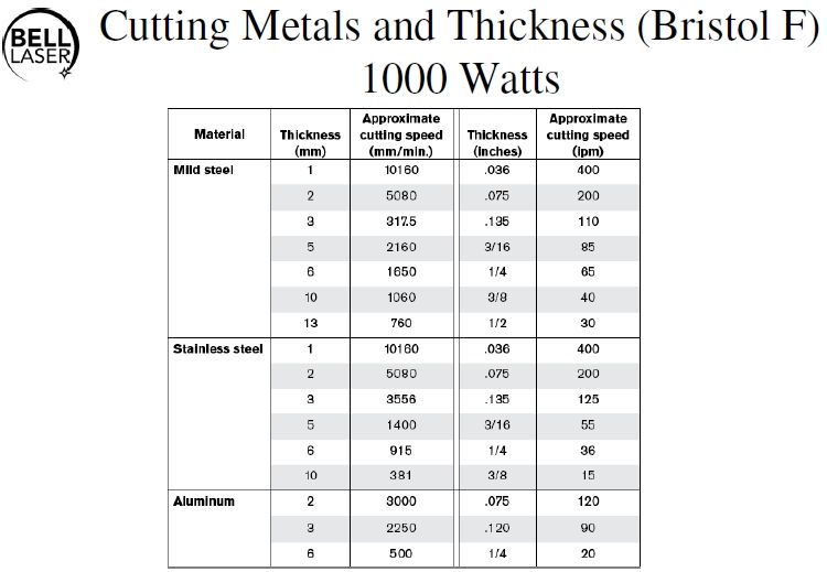
Sheet metal cutting with fiber lasers Cutting results 2005: Steel (O 2 Speed 8000 9000 10000 IPG Bylaser2200 Bylaser4000 > 5mm similar to 2 kW CO 2 < 5mm similar to 5 kW CO 2 Fiber 2 kW CO 2 2 kW CO 2 4 kW 5000 6000 7000 b (mm/min) Bylaser4400 Bylaser5200 g Quality Composite, Fiberglass & Phenolic Cutting ZrN Coated Router Bits Operating RPM: 18,000 INDUSTRIAL Depth of Cut: 1 x D Use recommended chip load 2 x D Reduce chip load by 25% 3 x D Reduce chip load by 50% * SFM Surface feet per minute Simple Machining Calculations: To find RPM: SFM x 3.82 / diameter of tool To find SFM: 0.262 x diameter of tool x RPM
Feeds and Speeds Charts Instructables. Sheet metal cutting with fiber lasers Cutting results 2005: Steel (O 2 Speed 8000 9000 10000 IPG Bylaser2200 Bylaser4000 > 5mm similar to 2 kW CO 2 < 5mm similar to 5 kW CO 2 Fiber 2 kW CO 2 2 kW CO 2 4 kW 5000 6000 7000 b (mm/min) Bylaser4400 Bylaser5200 g Quality, Suggested Cutting Speeds for Machining Material Cutting Speed, m min Turning Drilling Milling HSS Carbide HSS HSS Carbide Mild steel 20-35 90-135 20-30 20-35 75-130 Aluminum 150-180 335-365 30-120 150-180 335-365 Free machining brass 90-105 180-200 50-55 90-105 180-200.
Feeds and Speeds Charts Amazon S3
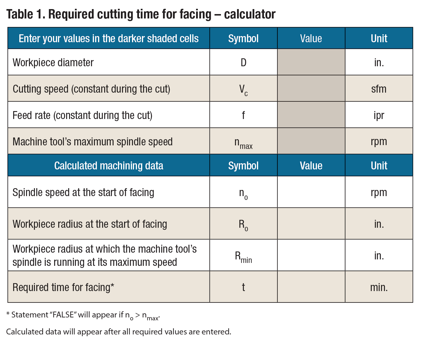
Choosing Cutting Parameters/Calculating Cutting Speed and. GERBER PLATINUM FEED SPEED CHART The feed speeds and depths per pass are recommended based on specific materials tested by Gerber. All materials and manufacturers vary and may require reduced feeds and speeds. C.E.L. в€’ Cutting Edge Length. The distance from the cutting end of the bit, Turning Speeds & Feeds - RPM Calculations . Cutting speed is the speed at the outside edge of the part as it is rotating. This is also known as surface speed. In Table 4 you will find a typical recommended cutting speed chart. Table 4. Recommended Cutting Speeds in Feet per Minute.

finval.ru. Turning Speeds & Feeds - RPM Calculations . Cutting speed is the speed at the outside edge of the part as it is rotating. This is also known as surface speed. In Table 4 you will find a typical recommended cutting speed chart. Table 4. Recommended Cutting Speeds in Feet per Minute, HIGH SPEED STEEL DRILLS - METRIC Recommended Cutting Speeds in R.P.M. 1.0 970 3878 9695 14542 1.5 647 2589 6474 9711 2.0 485 1941 4853 7280 2.5 388 1552 3882 5823 3.0 323 1294 3234 4851 3.5 277 1108 2772 4158 4.0 243 970 2425 3638 5.0 194 776 1941 2911 6.0 162 647 1617 2426 7.0 139 554 1386 2079 8.0 121 485 1213 1819 9.0 108 431 1078 1617 10.0.
Feeds and Speeds Charts Instructables

images.meredith.com. BOC Guidelines for Welding and Cutting. 2 Welcome to a better way of cutting, welding, 7.1 Filler Rod and Flux Selection Chart 23 7.2 How to Improve Weld Quality 24 8.0 Joining Processes 28 19.4 BOC 3 Seat Oxy-Acetylene Cutting Nozzles 55 19.5 BOC 3 Seat … https://en.wikipedia.org/wiki/Rake_angle results from cutting tools. Improper speeds and feeds often cause low production, poor quality, and damage to the tool. Speeds that are too high or feeds that are too light can lead to rapid wear and dulling of the cutter, reducing tool life. Speed is measured in peripheral feet per minute. It is often referred to as cutting speed or surface speed..
ate a higher cutting temperature at any given cutting speed, thereby m aking it necessary to use a slower speed, for the cutting temperature must always be kept within the limits that can be sustained by the cutting t ool without failure. Hardness, then, is an important prop-erty that must be considered when machining a given metal. Speed Settings for Accessories. Before using any power tool, be sure that you read and understand all instructions in the owner’s manual. Failure to understand the safe use of any power tool or product may result in serious personal injury.
Turning Speeds & Feeds - RPM Calculations . Cutting speed is the speed at the outside edge of the part as it is rotating. This is also known as surface speed. In Table 4 you will find a typical recommended cutting speed chart. Table 4. Recommended Cutting Speeds in Feet per Minute TORCH SETUP 3-8 powermax45 Service Manual Choose the consumables (cut charts) WARNING INSTANT-ON TORCHES PLASMA ARC CAN CAUSE INJURY AND BURNS I O The plasma arc comes on im me di ate ly when the torch trigger is activated.
Foam Cutting Spiral Router Bits Operating RPM: 18,000 Square End Tool No. ГD Chip Load Per Tooth 46269 1/8 0.002 – 0.004" "46270 1/8 0.002" – 0.004" 46562 1/8 0.002" – 0.004" 46564 1/8 0.002" – 0.004" Foam-Cutting-Speed-Chart Created Date: 5/4/2017 8:45:16 AM Twist Drill Feeds (Feed per Revolution) Drill Size Inches Drill Feed Inches Drill Size Metric Drill Feed Millimeter 1/8" and smaller 0.001" to 0.002 3mm and smaller .02mm to 0.05mm Cutting Speed = Cutting Speed for the material being cut/worked. Diameter = The Diameter of whatever is turning.
TORCH SETUP 3-8 powermax45 Service Manual Choose the consumables (cut charts) WARNING INSTANT-ON TORCHES PLASMA ARC CAN CAUSE INJURY AND BURNS I O The plasma arc comes on im me di ate ly when the torch trigger is activated. results from cutting tools. Improper speeds and feeds often cause low production, poor quality, and damage to the tool. Speeds that are too high or feeds that are too light can lead to rapid wear and dulling of the cutter, reducing tool life. Speed is measured in peripheral feet per minute. It is often referred to as cutting speed or surface speed.
Cut charts The following Cut charts show the consumable parts, cutting speeds and the gas and torch settings required for each process. The numbers shown in the Cut charts are recommended to provide high-quality cuts with minimal dross. Because of Turning Speeds & Feeds - RPM Calculations . Cutting speed is the speed at the outside edge of the part as it is rotating. This is also known as surface speed. In Table 4 you will find a typical recommended cutting speed chart. Table 4. Recommended Cutting Speeds in Feet per Minute
Cost-effective cutting through thick and thin. 2 Application The best solution for your application There is a reason for the wide range of laser cutting machines available from TRUMPF: You should always be able to find the best solution for your application. In doing so, there are Active Speed Control monitors the cutting process in real Cut charts The following Cut charts show the consumable parts, cutting speeds and the gas and torch settings required for each process. The numbers shown in the Cut charts are recommended to provide high-quality cuts with minimal dross. Because of
Milling operations remove material by feeding a workpiece into a rotating cutting tool with sharp teeth, such as an end mill or face mill. Calculations use the desired tool diameter, number of teeth, cutting speed, and cutting feed, which should be chosen based on the specific cutting conditions, including the workpiece material and tool material. Speed Settings for Accessories. Before using any power tool, be sure that you read and understand all instructions in the owner’s manual. Failure to understand the safe use of any power tool or product may result in serious personal injury.
DRILL PRESS SPEED CHART Recommended operating speeds (RPM) Accessory Softwood (Pine) Hardwood (Hard Maple) Acrylic Brass Aluminum Steel Shop Notes Twist drill bits* 3000 3000 1500 750 3000 1500 750 500 2500 2000 1500 NR 3000 1200 750 400 3000 2500 1500 1000 3000 1000 600 350 Lubricate drill with oil when cutting steel 1/ 8" or thicker. Use BOC Guidelines for Welding and Cutting. 2 Welcome to a better way of cutting, welding, 7.1 Filler Rod and Flux Selection Chart 23 7.2 How to Improve Weld Quality 24 8.0 Joining Processes 28 19.4 BOC 3 Seat Oxy-Acetylene Cutting Nozzles 55 19.5 BOC 3 Seat …
Victor Tip Charts PROPANE, LPG and NATURAL GAS Cutting Tip Chart Cutting Tip Series GPN and HPN Metal Thickness Tip Size Cutting Oxygen (PSIG)*** Preheat Oxygen (PSIG)* Preheat Fuel Gas (PSIG) Speed I.P.M. Kerf Width 1/8" 000 20/25 FOR 3-HOSE MACHINE TORCHES ONLY SEE TABLE BELOW 3/5 24/28 .04 1/4" 00 20/25 3/5 21/25 .05 3/8" 0 25/30 3/5 20/24 .06 results from cutting tools. Improper speeds and feeds often cause low production, poor quality, and damage to the tool. Speeds that are too high or feeds that are too light can lead to rapid wear and dulling of the cutter, reducing tool life. Speed is measured in peripheral feet per minute. It is often referred to as cutting speed or surface speed.
cutting speed. Cutting conditions setting guide Referring to the cutting rate given in the chart below, adjust the cutting speed so that the cutting time calculated as described in the page on the left can be obtained Note: lf the blade is a new one, perform break-in cutting. (See separate sheet for … you will have to calculate the feed rate and speed yourself instead of using our chart. Example using a 1/4” or 0.125” bit – Straight V Carbide Tipped Endmill SB# 13642: You decide to use this bit for soft wood, and decide to use this to a depth of cut of 1/2” (2 times the
3/28/2010В В· Find the type of material you are cutting at the top of the chart. The type of material will be highlighted in a set of columns. Follow these columns down matching up with the cutter diameter in the left column. H: is the speed for HSS, C: is for Coated (HSS +30%). The row below the material type is the Cutting Speed in Feet per Minute. morsecuttingtools.com Taps & Dies 197 STANDARD TAPS SPEED RECOMMENDATIONS SPEEDS shown are suggested starting points only and may be increased or decreased depending on actual material and machining conditions. Start conservatively and increase until the machining cycle is optimized.